Home > Technical > Technical support
Technical support |
The frequency of the quartz crystal on the circuit board after the oscillation is measured, and the difference between the frequency and the required center frequency is obtained, so as to understand the frequency deviation error range of the circuit board. The formula of frequency offset error is as follows:
Frequency offset error = (measured frequency value central frequency value) / center frequency value x 1000000 (derived from ppm).
Example: if the center frequency is 24.000MHz, the measured frequency is 24.000048MHz, and the frequency offset error is +2ppm. Different functions have different frequency admissible errors, and the acceptable values of real time frequency (RTC) are between 0ppm and +/-10ppm, and the permissible error may be high and low depending on the function. It is very important to measure the frequency offset error of the oscillating circuit, because if the frequency of the actual output exceeds the frequency tolerances too much, it may result in the unreliable result of the system in the actual work. For example, the time of RTC is fast or slow, video images may turn from color to black and white, or communication systems cannot receive signal data because of the inability to synchronize.
The driving power refers to the power consumed by the quartz crystal unit, the unit is the micro watt (W), which can be measured by measuring the current flowing through the quartz crystal and then converting the power consumed by the quartz crystal. The measurement of power should be less than the maximum value of the crystal component in the specification. The calculation formula is: P (uW) = I^2 x Re an oscillating line must be designed to provide the appropriate power to let the quartz crystal unit start to start vibration and maintain oscillation. This power should be smaller and better. Besides being more energy efficient, it is also related to the stability of the circuit and the life of the quartz crystal. If the oscillating circuit provides high driving power, the nonlinear characteristics of quartz crystal will change, and the interface between the quartz / electrode / material will be deteriorated, and the oscillation frequency and the equivalent impedance change too much. Instability occurs when quartz crystals work at high driving power for a long time. In the quartz crystal unit of 32.768kHz, when the driving power is too large, it may cause the fracture of the internal tuning fork type crystal. For the MHz grade AT crystal, the frequency hopping phenomenon may be produced, and the life and reliability of the quartz crystal can be affected.
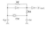
The negative impedance represents the oscillation condition of the oscillating line, that is, the health of the circuit, that is, the quartz crystal is not easy to vibrate under the drive. The negative impedance is not a real impedance value, but a resistance (RS) next to the quartz crystal. When the ESR in the quartz crystal is increased, the entire oscillating line can still be normally vibrate. The larger the negative impedance is, the better the better, which means that the oscillating line is easier to be lifted, and when the negative impedance is insufficient, it indicates that the oscillating line will have a slow vibration and may even lead to a state of non vibration. The basic value of negative impedance is 3~5 times of the maximum ESR value of quartz crystal.
