
Home > Technical support > Technical dictionary
Technical dictionary |

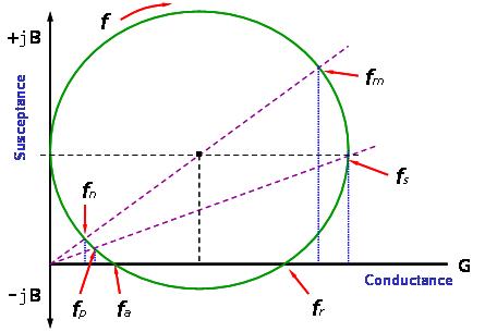
In terms of technical literature and product application, resonance of quartz crystal resonators has three sets of different definitions and resonance frequencies.
1. Series resonant frequency and parallel resonant frequency ( fs , fp )3. Maximum conductance frequency and minimum conductance frequency ( fm , fn )
(maximum admittance frequency minimum admittance frequency).The admittance (admittance) diagram of these three sets of frequencies can be seen clearly from the plural coordinates of (Fig. nine).
(1) Nominal Frequency and Tolerance
Under the correct matching of the oscillating lines, the frequency output from an oscillating line is called "nominal frequency". The frequency unit is generally expressed as MHz (megahertz, MHz) or kHz (Kilohertz, KHz).
In actual mass production and oscillating line applications, there are some frequency dispersion errors relative to the center frequency in the room temperature environment (25oC). The maximum dispersion of this type of frequency admissible error is generally expressed as ppm (parts per million) or% (percent).
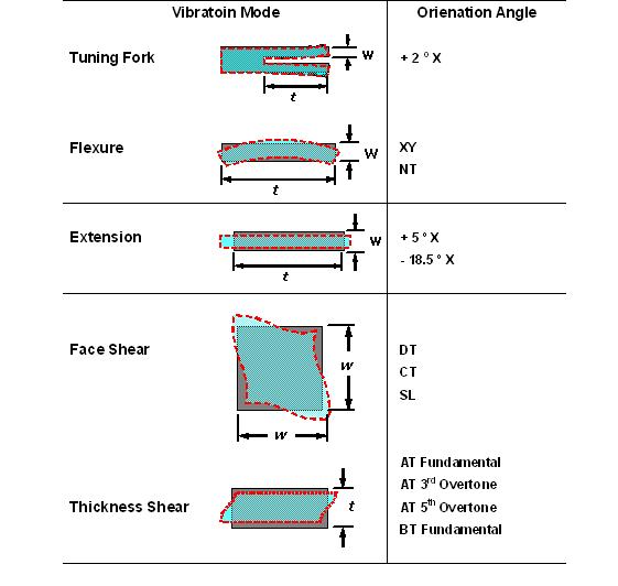
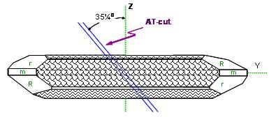
(2) Fundamental and Overtone Vibrations Mode
The quartz crystal resonators at the AT cutting angle exist mainly in the oscillating mode of the thickness shear. In the resonance, the high order frequency doubling resonances also exist between the electrode regions of the quartz crystal in addition to the basic wave oscillation, but the electrode of the piezoelectric material is the opposite of the electrical phase. Therefore, the frequency doubling of only odd times can occur, and the frequency doubling resonance of the even number of times (even number) will not exist in the quartz crystal resonance (Figure ten).
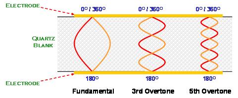
(Fig.10) Only odd number harmonic vibrations can be excited in crystal resonator
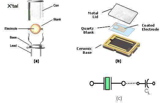
(3) Load Capacitance, CL
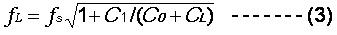
The "load capacitance" on an oscillating line is defined as all capacitance values encountered in an oscillating line from two terminals of a quartz crystal resonance. On line, the load capacitance can be connected with a quartz crystal resonance in parallel or in series. An oscillating line connected in parallel mode. The size of the load capacitance (CL) affects the nominal frequency characteristics.
The resonant frequency of this load capacitance parallel circuit is expressed in fL. :
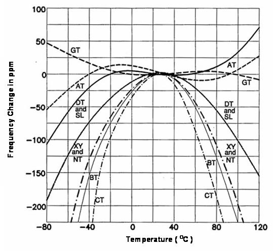
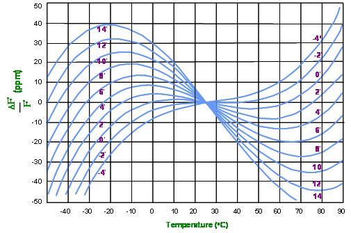
(4) Frequency-Temperature Stability
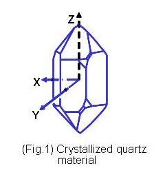
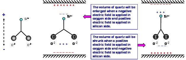
The frequency of quartz changes because of the temperature change, which is due to the different thermal expansion coefficient of the quartz material in the axis of each coordinate. When the temperature changes, the axial lattice distance of each axis varies a little. When the different cutting angles are quoted, the variations of the different oscillation modes are also different.
The design of the shear oscillating mode with the thickness of the AT cutting angle is generally used as the frequency of 25 degrees centigrade as the reference temperature point to define the stability of the frequency variation within the temperature range of the working environment. At the same time, the temperature range of the working environment should be defined together with the corresponding working environment temperature range.
The frequency of a quartz frequency element has a characteristic of temperature stability, as well as the nominal frequency error, with ppm or% as a measurement unit. The frequency temperature characteristic curve of the component has a great relationship with the cutting angle of quartz, the oscillating mode, the surface treatment and the outer size. In addition, the load capacitance (CL) on the oscillating line, The characteristics of driving power (drive level) will also affect the stability of the output frequency of the oscillation circuit to the temperature change.
(5)Equivalent Series Resistance , ESR
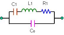
When the quartz crystal oscillates in series at FS, the C1 and L1 are counterpart to the opposite phase, and the dynamic branched arm (motional arm) of the entire resonance (admittance) is close to the minimum impedance value R1. at this time the whole quartz crystal resonance is only a resistive element. The resistance value R1 is the mechanical energy loss of the whole component. It contains quartz material, and all the energy loss of materials and packaging materials.
(6) Motional Capacitance C1 and Motional Inductance L1
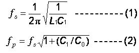
In Formula 1, the dynamic capacitance C1 and dynamic inductance L1 are interrelated with the frequency of series vibration and FS.
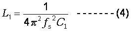
In the actual measurement system, we can only measure the dynamic capacitance C1 and the serial frequency of FS. The dynamic inductance L1 is calculated by formula (4).
(7) Static Capacitance or Shunt Capacitance, Co
The static capacitance, Co, is mainly free to use quartz wafers as the main capacitance of the dielectric material and the two electrodes; the other a small part of the static capacitance comes from the capacitance between the conductive materials connected by the quartz chip and the wiring and the capacitance of the package shell.
The static capacitance is measured at a range of far lower than the oscillating frequency to avoid the dynamic capacitance affected by the oscillating frequency. Formula (5) is a mathematical expression of the static capacitance.
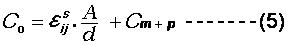
In the formula (5), A represents the area of the electrode; D represents the thickness of the quartz crystal; the epsilon is the relative dielectric value of the quartz crystal; Cm+p is the other capacitance value produced by the material.
(8) Drive Level
The driving power of quartz crystal refers to the power consumed by the quartz crystal resonators. Generally, it is expressed in a microwatt. The design of the oscillating line must provide the appropriate power to make the quartz crystal resonate to start and maintain the oscillation. The oscillation of the quartz crystal is the electrical impedance of the physical high frequency mechanical vibration and the oscillation. The value is below 10~100 ohm (depending on the frequency range and size). If the oscillating line provides high driving power, the nonlinearity of the quartz crystal and the interface between the quartz / electrode / material will deteriorate, and the oscillation frequency FL and the equivalent impedance R1 will be over changed. The quartz crystal is overdriven for a long period of time. With the low consumption of power demand and the trend of product reduction, the electrical impedance values of quartz crystal resonators are reduced and stable as a whole with the technology of quartz products in recent years. The energy is on the quartz crystal resonators. For most applications, the oscillating lines provide the maximum power of 10 ~ 100 microwatt (depending on the size and frequency of the quartz resonance) to the quartz resonators.
(9) Quality Factor, Q
For quartz crystal resonators, the electrical quality factor Q is a very important characteristic. The electrical quality factor can be expressed by the following formula (6).
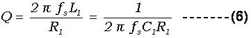
The quality factor of quartz crystal resonator can reach over 100 million.
(10) Pullability and Trim Sensitivity
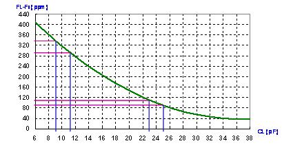
The resonance frequency of quartz crystal is applied on a parallel oscillating line. The oscillation frequency has a great relationship with the load capacitance CL. This can be seen in the previous formula (3). (Figure eleven) is a diagram of the change curve of the load capacitance CL on the FL frequency of the parallel oscillating line.
The frequency "traction rate" refers to the frequency variation of the frequency FL1 of the load capacitance CL1 to the frequency FL2 of the load capacitance CL2. In (Figure eleven) the frequency change value of FL1 (CL=24pF) and FL2 (CL=10pF). In this example, the frequency traction rate is 220 ppm. if we approach the CL1 and CL2 load capacitance values The tangent value of the curve is the sensitivity of a load capacitance .
In (Figure eleven), the frequency sensitivity of CL=24 pF is 10 ppm/pF, and the frequency sensitivity of CL=10 pF is 20 ppm/pF. in parallel lines. The smaller the load capacitance is, the higher the sensitivity of the frequency to the load capacitance. The higher the load capacitance, the lower the sensitivity of the frequency to the load capacity change. This is the quartz crystal common. When the oscillator is used on the VCXO line, a smaller load capacitance is used in the circuit design. On the other hand, a higher load capacitance will be used in the circuit design when the more accurate frequency signals are required.
(Fig. 11) Frequency variation vs. load capacitance
(11) AGING
"Aging" refers to the variation in the frequency of the quartz crystal resonators with the frequency of time in a certain period of time, with a unit of parts per million (PPM). The characteristic curves of aging in frequency and time are generally the changes in the exponential pattern. The frequency aging changes most. The large period is the first month after the quartz frequency component is made. After that, the frequency changes gradually decrease with time. There are several major factors affecting the aging characteristics of the frequency. For example, the packaging method, the type of material, the process temperature, the process control, the heat treatment process and the size and frequency of the product. Most of them need to define the short term (1~3 months) or long term (1~10) frequency aging needs.
(12) STORAGE TEMPERATURE RANGE
In addition to the temperature range in the previous working environment, another temperature related feature is the "Storage Temperature Range". This parameter refers to the maximum and minimum temperature range that the product can store in a static state. In this temperature range, the product must be guaranteed to be stored for a long time. It is also possible to work well in the working temperature range and conform to the specifications. This characteristic is closely related to the design and process design of the quartz crystal resonators, and should be carefully defined.
(13) Negative Resistance , - R
Negative impedance is the impedance characteristic value of the oscillating line at the oscillating frequency from the two terminals of the quartz crystal resonance. The oscillating line must provide sufficient amplification gain to compensate for the mechanical loss of the quartz crystal resonators at resonance. Negative impedance is not a quartz oscillator. Product parameter is an important characteristic parameter of oscillating line. From the point of resonance, it is the "negative impedance" of oscillating line.
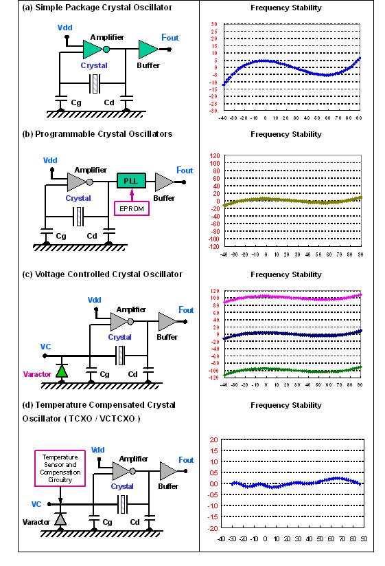
When the quartz resonators are integrated with an oscillating line or an integrated circuit (IC) together in a package, the power supply voltage is supplied externally, forming an active component output frequency signal, the so-called quartz crystal oscillator. The quartz crystal oscillator can be provided by different oscillating lines and output lines within a single package element. The reference frequency of different characteristic requirements (reference frequency). For example, a quartz time pulse oscillator SPXO (Simple Package Crystal Oscillator) or CXO (Clock Crystal Oscillator), a programmable quartz crystal oscillator PCXO, voltage controlled quartz crystal oscillator Ntrolled Crystal Oscillator), temperature compensates the quartz crystal oscillator TCXO (Temperature Compensated Crystal Oscillator) and the constant temperature slot to control the quartz crystal oscillator OCXO (Oven Controlled Crystal).
In order to meet the application needs, the oscillating lines within the quartz crystal oscillator are different in the basic or three frequency doubling modes. To reach the output frequency of the hundreds of megahertz, the post stage of the oscillating line can use the phase locked loop mode or the frequency doubling mode to increase the frequency of the quartz oscillation at a lower frequency. Bit and output waveforms also have different needs, such as CMOS, LVPECL, LVDS... .. And so on. These specifications should be carefully defined.
In Figure twelve, several stability diagrams of quartz oscillator output frequency for temperature changes are provided.